
Mixing 101: Baffled by Baffles?
How Baffle Configuration Can Optimize Industrial Mixing
In our previous posting on configuring your mixer, we learned that the tank type and volume, viscosity, specific gravity and the process are key factors the mixing process. In this article, we dive into how baffle configuration and mixer mounting can prevent the undesirable flow pattern of swirling.
Let’s look at a common tank configuration: an un-baffled cylindrical tank. If a mixer is center-mounted in this tank, what we see is a very inefficient flow pattern: the tangential velocities coming from the impeller cause the entire fluid mass to spin (Fig. 1). Basically, the entire fluid (and its solids) moves like a merry-go-round. In solid suspension applications, the solid particles will swirl around at the bottom of the tank: no axial (top to bottom) flow is created to lift them up and suspend them in the fluid.

There are three ways swirling can be prevented, and we’ve listed them by preference:
- Installing baffles in tanks
- Offset angle mounting of mixers
- Offset vertical mounting of mixers
Using baffles or offset mounting techniques will generate unbalanced loads that will act on the mixer shaft. When these unbalanced loads become significant, a heavier-duty agitator gearbox and bearing are needed. As a result, the mixer is more expensive.
Baffles are our first choice because the loads generated are much less than those generated by offset angle or vertical mounting techniques. For smaller tanks (<10′ diameter), offset mounting will work just fine, and the extra cost associated with compensating for unbalanced load is minimal. For larger tanks, however, it becomes expensive to go with the heavier-duty mixer, and installing baffles is more cost effective.
Baffle Design
Baffles are long, flat plates that attach to the side of the tank to prevent swirling & promote top to bottom fluid movement. They are most commonly used for blending and solid suspensions because these applications often use vertical, cylindrical tanks that tend to create swirling patterns, regardless of the type of impeller being used.
The flow pattern illustrated here shows that the use of baffles results in excellent top-to-bottom circulation and great radial mixing.

Baffle Configuration
Baffles should be designed using the following guidelines (Fig 3):
- Number of baffles = 3 to 4 (4 is ideal, but 3 will result in sufficient mixing). Adding any more than 4 baffles will not result in any significant mixing improvement.
- Width = 1/12 of the tank diameter (i.e. for a 12’ diameter tank, the baffle width will be 1’)*
- Length = starts approximately 6 inches from the bottom and ends just above the maximum liquid level
- Mount Position = 1/6 of the baffle width off the tank wall**. (i.e. a 1’ wide baffle will be mounted 2” off the tank wall)
* For medium viscosity mixing (ie. viscosities over 3,000 cps or Reynolds Numbers from 10 to 10,000), we often reduce the width of the baffle to 1/2 of standard width
** When agitating slurries, baffles are often located up to 1/2 of their width from the vessel wall to minimize accumulation of solids on or behind them.

Going Baffle-less
There are instances where baffles are not required
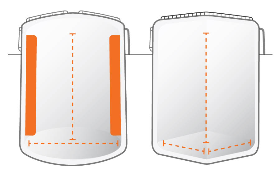
- Square or Rectangular Blending Tanks: Most blending applications that use square/rectangular tanks don’t need baffles because these tanks are self-baffling. However, they are less suitable for solid suspension because “dead spots” are formed in the corners.
- High Viscosity Mixing: For high viscosity mixing (viscosities over 5,000 cps or Reynold’s Numbers < 10), the same power is consumed by the impeller, with or without baffle, so they’re seldom used.
Mixer Mounting
Offset Angle Mounting
With axial-flow impellers, an angular off-center position where the impeller is mounted approximately 10-15° from the vertical, can be used (Fig. 4). It’s worth noting that the angular off-center position used with axial impeller units is usually limited to those delivering 3 HP or less. The unbalanced fluid forces generated by this mounting can become severe with higher power.

Offset Vertical Mounting
If an angle mount is not available, the mixer can be offset while being placed vertically in the tank. The rule of thumb for this is to offset the mixer on the x-axis, 1/6th of the total tank diameter. So, for a 60″ diameter tank the mixer would be offset 10” from center (60”/6 = 10”).

As you can see, baffle configuration and mixer mounting have a significant impact on the mixing process. When engineered correctly, the right application of these techniques can decrease costs & increase equipment life while optimizing the mixing process.